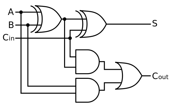
Full Adder Logic Diagram
Full-adder circuit, the schematic diagram and how it works – deeptronic Vhdl code for full adder using behavioral method Digital logic design: full adder circuit
Full Adder Circuit: Theory, Truth Table & Construction
Adder circuit logic using digital boolean implementation diagram implement function Adder half xor logic ripple rangkaian adders transistor kombinasi Full adder
Adder logic projectiot123 introduction binary carry sum outputs
Adder logic pla inputs explainWhat is half adder and full adder circuit? Full adder circuit diagramAdder fc2 uhighlsu.
Adder circuit diagram schematic bit works figureAdder binary logic input output sum xor theorycircuit boolean diagrams derived following inputs Adder bit ic datasheetAdder half circuit carry ripple bit schematic diagram gate truth table delay electronics doubt xor without representation shown single below.
![2 bit adder truth table](https://i.ytimg.com/vi/q5JMqVeJ8k8/maxresdefault.jpg)
Adder vhdl behavioral logic explanation
Adder half two using truth table diagram logic gate faFull adder circuit: theory, truth table & construction Full adder logic diagramHalf adder.
Full adder circuit diagramCd4008 4-bit full adder ic pinout, working, example and datasheet 2 bit adder truth tableAdder circuit logic gates construction binary circuits equations sourav gupta.
![Full Adder - Truth table & Logic Diagram | Electricalvoice](https://i2.wp.com/electricalvoice.com/wp-content/uploads/2018/05/full-adder-using-two-half-adder.jpg)
Adder logic
Half adder logic diagram and truth table / obe assignment: digitalAdder logic half implementation Half adder and full adder circuitAdder half circuit diagram table block electronics input outputs along.
.
![What is Half Adder and Full Adder Circuit? - Circuit Diagram & Truth](https://i2.wp.com/circuitglobe.com/wp-content/uploads/2015/12/HALF-ADDER-FULL-ADDER-FIG-2-compressor.jpg)
![Full Adder Circuit Diagram](https://i2.wp.com/theorycircuit.com/wp-content/uploads/2018/07/full-adder-circuit.png)
![Digital Logic Design: Full Adder Circuit](https://4.bp.blogspot.com/-NIy45k3TuEE/TkouUTvUOZI/AAAAAAAAAG8/SQiB48Yi_UQ/s1600/550px-Full-adder.png)
![Adder - Classifications, Construction, How it Works and Applications](https://i2.wp.com/electricalfundablog.com/wp-content/uploads/2020/01/Full-Adder-Block-Diagram-and-Logic-Diagram.jpg?ssl=1)
![VHDL code for full adder using behavioral method - full code & explanation](https://i2.wp.com/technobyte.org/wp-content/uploads/2018/09/Full-Adder.png?ssl=1)
![CD4008 4-Bit Full ADDER IC pinout, working, example and datasheet](https://i2.wp.com/microcontrollerslab.com/wp-content/uploads/2019/11/full-adder.png?resize=550%2C350&ssl=1)
![half adder - Electro](https://1.bp.blogspot.com/-iaCjZBR4iHo/Udp2HhDmObI/AAAAAAAACqc/hlOuaXymUO8/s1600/logic+diagram+binary+full+adder.png)
![Full Adder Circuit: Theory, Truth Table & Construction](https://i2.wp.com/circuitdigest.com/sites/default/files/projectimage_tut/Full-Adder-Circuit.png)
![Half Adder Logic Diagram And Truth Table / OBE Assignment: Digital](https://i2.wp.com/projectiot123.com/wp-content/uploads/2019/07/What-is-Full-Adder.jpg)
![Half adder and Full adder circuit - Electronics Engineering Study Center](https://i2.wp.com/www.electronicsengineering.nbcafe.in/wp-content/uploads/2014/09/half-adder-1.png)